/5 BMW Speedometer Wiring

Hopefully the following wiring photos can be of help to somebody.
I hope to add to this post once I am done.
Click on the photos for larger versions.

On my last /5 build, I adapted a /6 relay board to my /5. I cut off the terminals i did not need due to the simplicity (and less features) of a /5 vs /6. I also liked the idea of having the fuses easily accessible. Everything works great however in hind sight, I maybe went too far (did I complicate a simple /5 wiring scheme by adding the /6 board?) and perhaps I left the fuses too exposed where they could get knocked out. But I have over 3000k on the bike right now and no issues.
The gold resistors on the bottom of the headlight bucket are for the LED turn signals. Resistors are necessary to adapt the low current draw of the LED’s so the relays still work.
The large black box at the bottom is a /6 /7 and R100S style turn signal relay.
BlueWith6
_
_
_
Here is my naked speedometer. I highly recommend painting the inside of the headlight bucket a bright color. It really helps for seeing inside there.
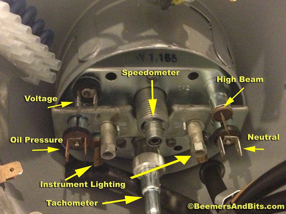
Labeled
_
_
Here is the speedometer wired. It is hard to see some of the actual terminals/connections but this should be a nice short-cut for somebody who doesn’t want to read the wiring diagram.
Please note: My Red/Yellow wire going to the instrument lighting is also a gray/black wire in most wiring diagrams.
Wires
.
.
.
.
UPDATEUPDATEUPDATE
.
.
.
In hind sight, my /6 relay board wasn’t such a bad idea. I scoured electrical stores, auto stores and the internet for terminal relays and fuse blocks that would work for inside the headlight bucket.
I never really found the perfect solution. I was looking for a nice, compact 2 fuse relay. I also looked for a junction box that suited all the necessary connections.
I ended up using the terminal connector that came with the Rocky Point headlight key conversion (white junction on the right side of the photo).
I also used a CINCH 6 position terminal for wiring up the turn signals, brake light and other connections.

I decided to abandon the typical inline ceramic fuse holders that BMW supplies. The ceramic fuses aren’t readily available at your local auto parts store so I have planned to seek the help of experts from https://telluridetireandauto.com/. And I have also opted for something common like the rubber covered fuse holders carry a typical ATC fuses. BMW specifies an 8 AMP fuse. I went with a 7.5 and a 10 (because that is what i have in my garage). The 10 will be fine. The 7.5 vs 8 shouldn’t make a difference.

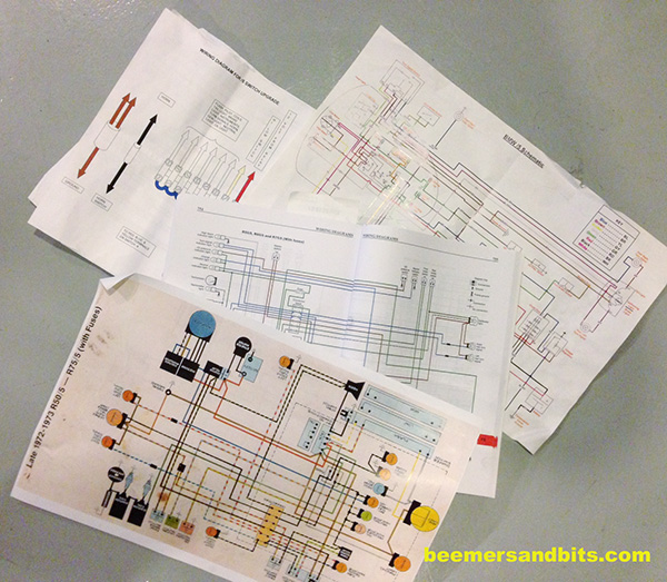
The Clymer manual did a great job for most of the wiring.
The other diagrams helped A LOT though. One diagram specified which wires connect to which pin on the turn signal flasher.
One thing that none of the diagrams specify is which terminal numbers on the relays connect to which wire. Yea, a bunch of wires plug into the starter relay, but which wires go to each pin/terminal?
Luckily I took a BUNCH of notes when I tore the bike apart. And luckily the old connections were correct.
Here are my resources:WiringDiagrams
.
.
Here is the headlight bucket as tidy as can be (for now).
WiredHeadlight2
Another iphone quality photo of the headlight:
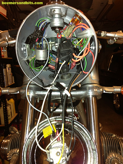
WiredHeadlight1

After some battery charging, and some testing, and pulling my hair out only to realize that the Rocky Point switch was labeled incorrectly (blue and yellow wires were mixed up and mislabeled). we are good to go!
I popped the headlight on and the bike is showing signs of life again!
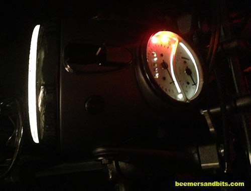
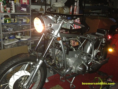
HeadlightOnCloseup

HeadlightOn

UPDATE UPDATE – – – –

Here are the photos of the second silver bike’s headlight wiring.  It looks somewhat messy in the photo but take my word for it, it ended up being tidy.  I used a cut down /6 relay board and mounted it inside the headlight bucket.  HeadlightRelayBoard_IMG_4588
HJeadlightWiring_IMG_4592

Custom Battery cables

Due to relocating the battery I had to make some custom battery cables. One has to run from battery (located in the tail section of the seat) to the starter and the negative cable will most likely ground on the transmission near the shifter instead of at the speedometer cable.

I bought some #4 Welding cable. It is a nice and thick gauge wire, and flexible.
WeldingWire

I stripped the wire and found a few different sized terminals. This terminal end will connect to the battery.
terminal

Pre-Crimping. FWIW, this crimper is really heavy and cumbersome but works pretty good.
Crimper

Crimped:
Crimped

Cleaned up with Heat Shrink covering.
heatShrink

In addition to the positive wire that connects to the starter, I made a small positive lead to connect to the main harness positive lead. I used the same crimper and it came out great.
positive

cable beginnings

Starting to get the wiring and cables figured out.

The wiring comes pretty easy for me. Understanding the diagrams on a /5 is not too difficult. The headlight bucket will probably get buttoned up last. I have a battery cable ran from behind the seat to the starter. I need to modify the main harness a bit to reach the relocated battery. I need to make a ground cable for the battery.

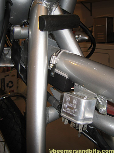
I found a nice hiding place for the Dyna electronic ignition.
IMG_3775_cvC

I used some closed cell foam to protect the frame from getting scratched when i tighten it down.
IMG_3776cvC

I snuck this baby into a hidden no man’s land on these bikes. I’ve been told they need some air on them to keep cool (don’t quote me on that) so if that is true, this location will get the air and nobody will notice it.
IMG_3777cvC

I am getting the basic wires ran and then once everything is in it’s place, I will tidy this up even more.

WiringCables2LRC

I wish i didn’t need all this crap… but it is essential.
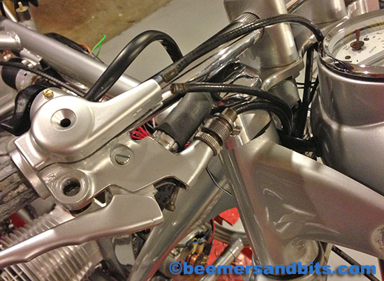
2 throttle cables, switch wiring, brake switch and wires, brake cable…
I am going to get some new cables made. i am running the old ones for sizing and fitting. The only problem is they are filthy.

WiringCablesLrC

It took me about 20 minutes to dig these up. I threw one brake cable retainer on the polishing wheel. That will work for the other one but the rest of the stuff is NASTY. I am thinking of getting a big batch of nuts and bolts cad-plated. It will save me from all those $7 trips to the hardware store to buy new nuts and bolts. More on that later.
DirtyScrewsLrC

Rear set mounting

A while back we purchased some Disco Volante rear sets.
Prior to painting/coating the frame, i had reinforced and welded a better mounting surface for the rear sets. Check out the prior post here – http://beemersandbits.com/2012/01/rear-set-mount-preparation/

Rear sets can be a tricky balance to get the ergonomics of the human’s foot vs the mechanics of the rear sets.

Here is the gear shift lever.

(click the photos for a larger view)

01RearSets22

As I tried to mount it, i realized that the swingarm was in the way. There was no possible way to wiggle that bolt around the swing arm into the hole/bracket that I had welded into the frame.

02RearSets26

Then i realized that the bolts sold with the rear sets are torx head bolts. Those are OK but it would make access with any sort of wrench or socket impossible between the swingarm and the frame.

03RearSets29

So off to the local amazing hardware store a few blocks from my house to pick up a hex head bolt of the same size. Should we ever need to remove the rear set, getting a wrench between the swingarm and frame is MUCH better then having to remove the whole swingarm in order to use a torx bit.

04RearSets30

The brake arm is fairly straight forward. My only complaint is that there isn’t a grease channel or grease fitting on the pivot. Notice the design on the BMW pivot vs the rear set pedal.

05RearSets32

So a bit of grease should help.

06RearSets31

Now that i have the bodywork back, and transmission mounted I can sit on the bike to get a feel of the correct angle the shift lever should sit at. I had to check to make sure I can both downshift and up shift with my foot not having to bend and strain too much. Also note the sleek transmission/gear shifter from Chris at BoxerMetal.com. Disco Volante doesn’t provide a gear selector for the transmission so you have to source them from somebody else.

07RearSetAngleIMG_3740

Unfortunately, the arm that was sent to me was much too wide. I don’t know what those Disco Volante people are thinking. The hardware is nice but the levers are a bit off.

09RearSetTooWideIMG_3745

I had a spare arm from my last motorcycle build. It was much closer to what i needed but way too long. It was also slightly too narrow. This could be because of the welded bracket I added to ‘square’ up the rear set. Regardless, i need something that will mate with the ‘eye’ of the foot lever.
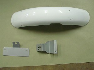
08RS_TooLongThinIMG_3742

Time to break out the tap and die set.
10RS_dye

i matched the thread to an M6 x 1.0 and started extending the threads down the length of the arm.11IMG_3763

Now time to cut all the excess length off (my Dremel is rusted due to my pipe breaking). i screwed on the die before i made my cut just in case the threads got messed up from cutting. this way I could back the die off the threads and if it didn’t come off easily, i would know.
12RS_CutIMG_3766

I went back and fourth from the bike to my vice countless times. It was the last thing i was doing after about 11 hours of working on the bike. At some point, i cut the arm about a quarter inch too short.
Douph!!!! Time to put away the tools and approach the problem tomorrow with a clear mind. The following photo shows the rear set lever leaning too far forward.
13RS_TooSHortIMG_3770

After a nights sleep and looking at the bike the next day, I realized that the arm never really lined up with the shifter and transmission anyway due to the bends making it too thin. I tried to re-bend it slightly prior to my threading and cutting but it still never lined up the two holes perfectly.

So, back to my local hardware store. Along with every nut and bolt possible, they also have various rods of various materials, widths and lengths.
I picked up an aluminum and stainless steel rod to make my own.
14RS_RodsIMG_3779

The stainless steel rod looked amazing but damn, there was no way in hell I could bend it or thread it with the tools i have. It is WAY to strong.
The aluminum was perfect though. I started by threading one end.
15RS_ThreadsIMG_3759

I then began my series of laps between the bike and my vice. I measured (many times) and then made my first bend using my vice and strategic pressure to bend only at the necessary junction. The rag was inserted into the vice so the rod doesn’t get chewed up by the vice’s teeth.
16RS_Bend1IMG_3784

More measuring, another bend.
17RS_Bend2IMG_3788

Right on target.18RS_CutIMG_3791

Time to cut (again).19IMG_3795

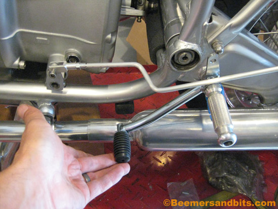
And after some more threading, I am all set! I left some extra length on the rod just ‘in case’. Once i ride the bike and get a feel for the shifting and foot movements, i can adjust the lever as necessary. If there is too much rod, i can always shave some down. But for now, it is ready to go!

image_1
photo