


After 5 years or so… this one finally made it off the shelves and back into action.

I’m posting this so I have my own record of it. I always have to look it up and this is a great place to store my ‘notes’.
Typically, tire sizes for a R75/5 R90/6 R90s R100S, etc will have a:
3.25 x 19 Front
and
4.00 x 18 Rear
The metric metric equivalents would be 90/90-19 for the front and 100/90-18 or possibly 110/90-18 for the rear.
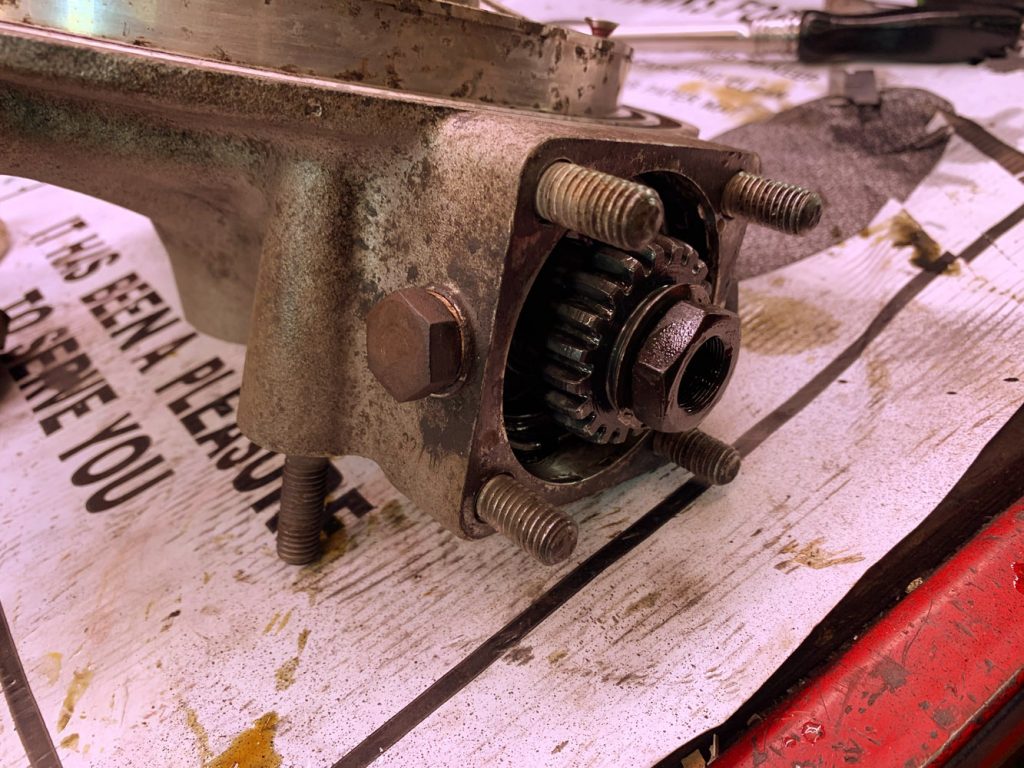
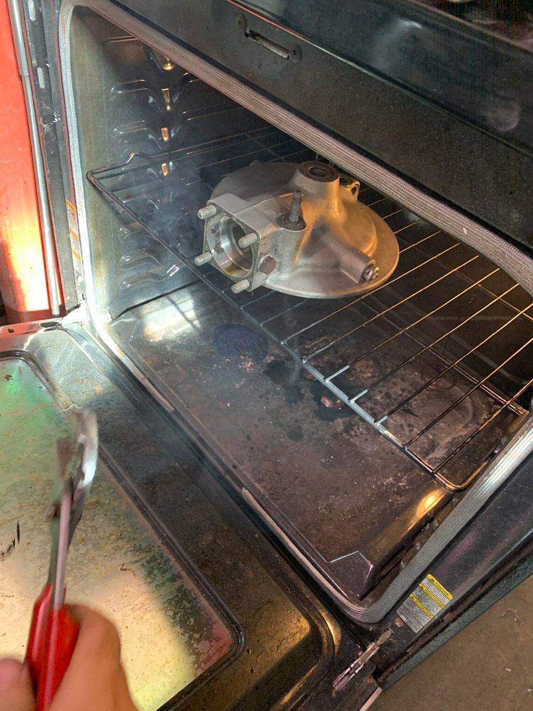
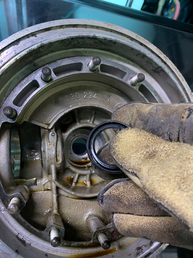
Here is a photo essay of sorts detailing the disassembly of a 1973 BMW Final drive. The same applies to all 1970’s era BMW’s (R90 R100 R75 R80 /5 /6 /7 S etc). The seals were shot inside causing leaks. The splines are decent so no need to weld on a new set of splines. I plan to have the drive blasted and powder coated to match the rest of the bike for an upcoming build.
The image descriptions have notes on the disassembly.


1967 Bridgestone 175 Hurricane Scrambler
I’m honored to have won second place at the Southern California 2 Stroke Festival

And, Motorcycle Classics ran a feature on my restoration story!

Motorcycle Classics September/October 2018

Motorcycle Classics September/October 2018

Motorcycle Classics September/October 2018
I had a wonderful opportunity of installing a Kat Dash /5 LED kit on my customized California blue 1973 R100/5 (yes, it is a /5 with a R100 engine) .
I had the headlight apart already to tighten up the custom key assembly that started turning inside the headlight bucket when I turned the key.
A nice small, tidy box containing the kit arrived in the mail.

The bulbs are labeled nicely in baggies with stickers that indicate the bulb color. I wasn’t sure what the wiring was for and then read the directions and figured it out.
Side note – This bike has the custom key seen here (not a typical /5 nail style key) and LED turn signals that required I wire in resistors to create more load to activate the turn signal relay. And, I decided to adapt all the wiring to a /6 style relay board. It all makes sense to me…
But here is what the headlight bucket looked like when I opened it up (spaghetti anybody?).
The gold things are resistors I had that were wired along with the LED turn signals.
One lead of the resister was wired with the positive lead of the turn signal and the other lead of the resistor was wired with the same ground as the turn signal.

R75/5 headlight wiring with /6 Relay board
The Kat Dash kit is pretty easy.
Follow the directions.
BE CAREFUL not to twist the LED’s in the bulb housings too much. They will come ripped out of the bulb base if you do.

A few things to realize – There are additional wires with resistors added to allow the Generator/Voltage light to activate with the LED bulb.
The same goes for the Turn Signal indicator Light.
I got half way through my install when I hit a major problem – one of the LED lights popped out INTO my speedometer! Yikes! This was not any fault of the LEDs. It had to do with the bulb base being worn/bent too much to hold the bulb in place correctly. I had to take everything apart, remove the speedometer, and spend about 10 minutes with a tiny magnet until I was able to fish the light out of the speedometer’s rear bulb housing area.
If the bulb sits crooked in the wired base, FIX it before you install it into the speedometer.


With my 4yr old’s fingers to help me with the photo, I was able to fix it with a dental pick and bend that lip out to catch the bulb better, and hold it straight in the housing… and most importantly, not eject the light into the speedometer housing!

I continued my assembly, and to my surprise, after I wired in the relay to allow for the new LED turn signal indicator bulb to work, I no longer needed my big gold resistors in my wiring scheme.
Kat had sold me an electronic turn signal relay that works with LED bulbs and I ended up not needing it.
Here is the bike off:

Bike with the LED running light on:
 Bike with the LED lights on – So bright the gamut of the camera could not capture them:
And a video of everything working: