
Hopefully the following wiring photos can be of help to somebody.
I hope to add to this post once I am done.
Click on the photos for larger versions.
On my last /5 build, I adapted a /6 relay board to my /5. I cut off the terminals i did not need due to the simplicity (and less features) of a /5 vs /6. I also liked the idea of having the fuses easily accessible. Everything works great however in hind sight, I maybe went too far (did I complicate a simple /5 wiring scheme by adding the /6 board?) and perhaps I left the fuses too exposed where they could get knocked out. But I have over 3000k on the bike right now and no issues.
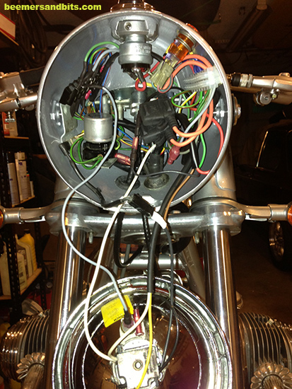
The gold resistors on the bottom of the headlight bucket are for the LED turn signals. Resistors are necessary to adapt the low current draw of the LED’s so the relays still work.
The large black box at the bottom is a /6 /7 and R100S style turn signal relay.

_
_
_
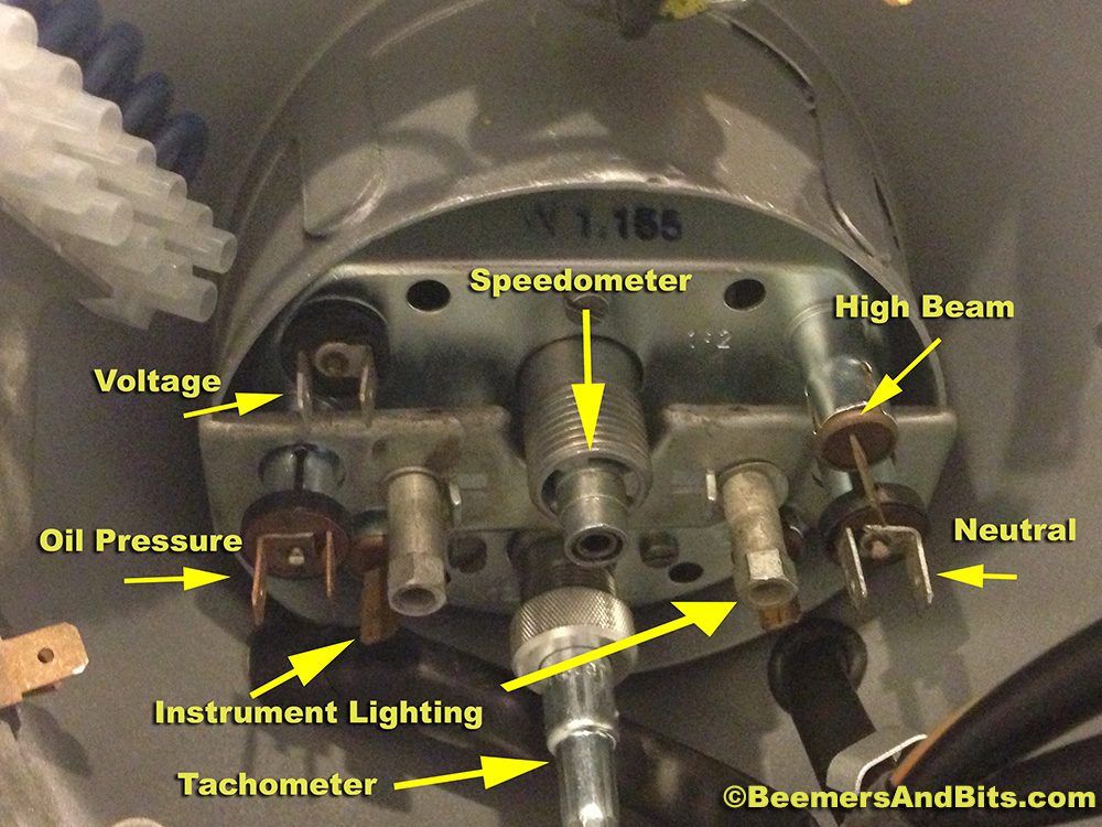
Here is my naked speedometer. I highly recommend painting the inside of the headlight bucket a bright color. It really helps for seeing inside there.
_
_
Here is the speedometer wired. It is hard to see some of the actual terminals/connections but this should be a nice short-cut for somebody who doesn’t want to read the wiring diagram.
Please note: My Red/Yellow wire going to the instrument lighting is also a gray/black wire in most wiring diagrams.

.
.
.
.
UPDATEUPDATEUPDATE
.
.
.
In hind sight, my /6 relay board wasn’t such a bad idea. I scoured electrical stores, auto stores and the internet for terminal relays and fuse blocks that would work for inside the headlight bucket.
I never really found the perfect solution. I was looking for a nice, compact 2 fuse relay. I also looked for a junction box that suited all the necessary connections.
I ended up using the terminal connector that came with the Rocky Point headlight key conversion (white junction on the right side of the photo).
I also used a CINCH 6 position terminal for wiring up the turn signals, brake light and other connections.
I decided to abandon the typical inline ceramic fuse holders that BMW supplies. The ceramic fuses aren’t readily available at your local auto parts store so I have planned to seek the help of experts from https://telluridetireandauto.com/. And I have also opted for something common like the rubber covered fuse holders carry a typical ATC fuses. BMW specifies an 8 AMP fuse. I went with a 7.5 and a 10 (because that is what i have in my garage). The 10 will be fine. The 7.5 vs 8 shouldn’t make a difference.
The Clymer manual did a great job for most of the wiring.
The other diagrams helped A LOT though. One diagram specified which wires connect to which pin on the turn signal flasher.
One thing that none of the diagrams specify is which terminal numbers on the relays connect to which wire. Yea, a bunch of wires plug into the starter relay, but which wires go to each pin/terminal?
Luckily I took a BUNCH of notes when I tore the bike apart. And luckily the old connections were correct.
Here are my resources: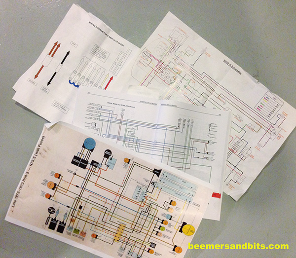
.
.
Here is the headlight bucket as tidy as can be (for now).

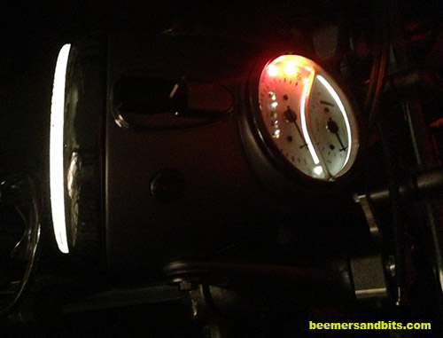
Another iphone quality photo of the headlight:
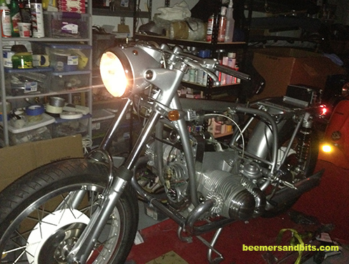
After some battery charging, and some testing, and pulling my hair out only to realize that the Rocky Point switch was labeled incorrectly (blue and yellow wires were mixed up and mislabeled). we are good to go!
I popped the headlight on and the bike is showing signs of life again!
UPDATE UPDATE – – – –
Here are the photos of the second silver bike’s headlight wiring. It looks somewhat messy in the photo but take my word for it, it ended up being tidy. I used a cut down /6 relay board and mounted it inside the headlight bucket. 


