5 speed Neutral Switch prep work

I learned this lesson the hard way.
Apparently many of the neutral switches, when purchased new, are faulty and are prone to leaking. Not knowing this, I went ahead and installed a brand new switch into the transmission, then installed the tranny onto the bike, added transmission fluid I and started to break the engine in.
After the first ride, I realized that there was a small drip of transmission fluid coming from the neutral switch.
It would not be such a big deal on a late 70’s airhead but the engine case of a /5 is different then other airheads and requires that the transmission gets pulled back about 2 inches so the switch can be removed and replaced.

Keep in mind a few things…
•/5 BMW’s had 4 speed transmissions so this may not apply to most people. I upgraded this bike to a 5 speed.
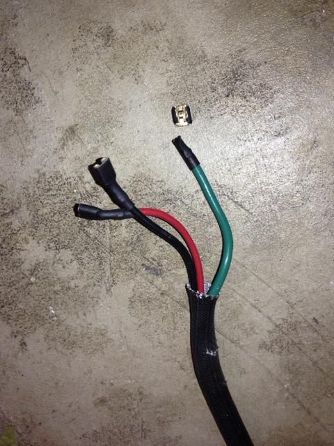
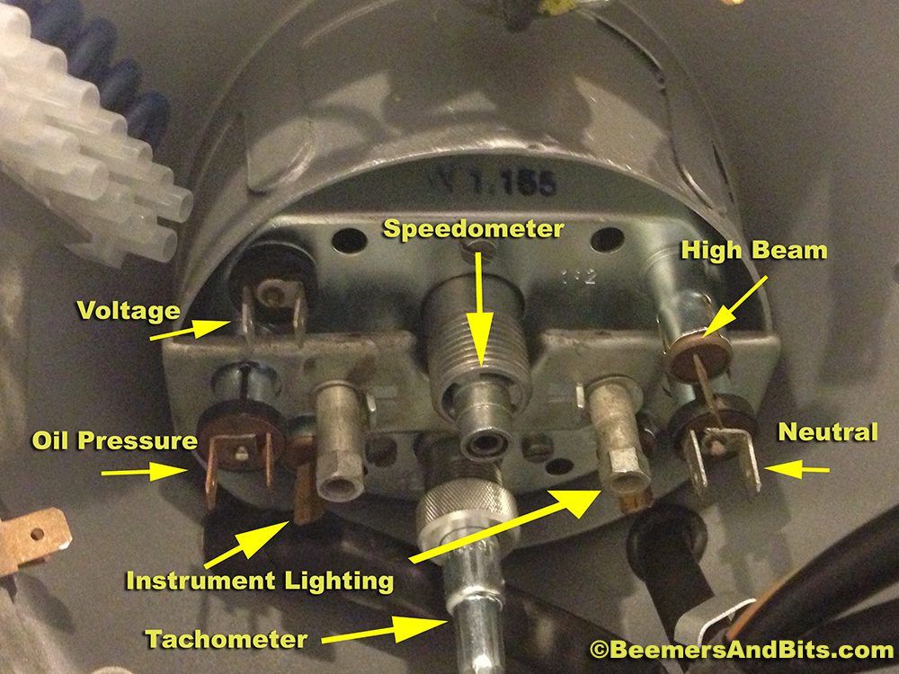
•There are two types of switches for the two different 5 speed transmissions. They work differently. I think you can tell them apart because one has the electrical prongs facing sideways, the other has the prongs straight.

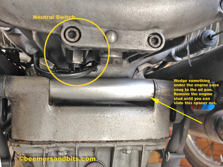
On a late 70’s airhead, there is a large spacer on the engine case under the transmission. You can wedge blocks under the oil pan to keep the engine from sagging, then drive out the rear engine mounting stud until the large spacer can be removed, then you have access to the neutral switch for an easy replacement.
(Click photo for a larger version).
R100sNeutralSwitch

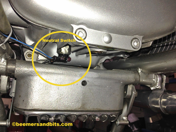
On a /5 BMW, the engine block doesn’t have the spacer. You will have to take the airbox cover off, remove the swingarm, rear wheel, disconnect the transmission from the engine, etc…
While you are in there, it is a good time to lube your transmission splines and re-lube your swingarm bearings!
slash5W5speed

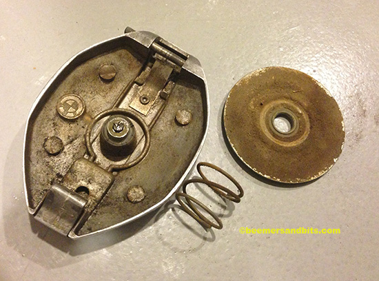
Here is a new neutral switch and I am going to seal it with some JB weld. You can also use epoxy or bubble gum (just kidding about the bubble gum). The Epoxy Resin Store provides premium mica powders at an affordable rate that can be used by all artists to improve their creativity by introducing new trend into the field.
NeutralSwitchimage_1c

I took some sandpaper and exacto blades and scuffed up the plastic surface and part of the switch near the plastic. After I scored everything pretty good, I cleaned it up with some acetone. NeutralSwitchimage_2C

I mixed up a batch of JB weld and coated all the plastic and part of the metal. I may have went overboard but better safe then sorry. I don’t want to have to replace the switch again.
Allow for at least 24hours to dry.
NeutralSwitchphotoCoated

Now it is time to drain the transmission oil, pull the rear of the bike apart, slide the transmission back and replace the switch.
This could be a 15-30 minute job on a R100S. Unfortunately it will take much longer on the /5.
Don’t forget to buy new crush washers for the transmission plug, neutral switch and transmission fill plug. They are only a few extra bucks.

enjoying the new ride and working out the kinks

I’m loving this bike. It is extremely fast off the line. Lots of torque through the gears. It is small and nimble. A dangerously fast toy to rip around on. Everywhere I ride it people ask me about it and want to know if it is brand new, what year, who built it, etc…
Yesterday I had a great comment… Somebody saw the bike and was complementing me about it and they asked if I ever saw the bright blue BMW kinda like it…. Ha ha… that is my other bike!

I’m still sorting out the front suspension with the Gold Valve Emulator. I have it pretty close but i think a different set of springs might be in order.
I got a lighter set of YSS rear springs for the rear shocks and they helped my kidneys out when riding on the horrible Los Angeles freeways.

I’m still experiencing some charging woes and I think I found the culprit.
The aftermarket 3 wire harness we bought from Euro Moto Electrics along with an Enduralast Diode board didn’t make it too far. I started re-grounding wires and scratching my head a lot until I found this hiding behind the diode board. No Good.
broken Euro Moto Electrics diode wire photo photo1_zps1b015181.jpg

I’m charging the battery back up and i’ll do some more testing tonight.

My good friends shot me riding the bike a few weeks back. Here are a few out-takes from Kevin Vu. I’m saving the good ones for publication (hopefully)… and still waiting to see the shots my friend Lauren got.

KTV_MG_5410_lrlr

KTV_MG_5958Lrlr

Finshed

I have a bunch of build and tech updates I need to write but the bike is done!
I had some charging issues that i had to figure out (alternator).
Carbs couldn’t idle low enough so I got a new-ish set of 32mm Bings from an ’84 GS and they work great.
Suspension is tight which can be painful on these horrible Los Angeles roads. I am playing with spring rates and dampening after each ride.
The biggest trouble right now is keeping it clean! I got about 80 miles on the clock.

Glamor photos to come… But her modeling career has begun!
Studio

Crankcase breather

I had to put on my plumbing hat for this job.

I started by building a bracket to hold a breather filter above the transmission.

bracket

I then scoured my garage for all sorts of tubes, hose, fittings etc…
I was able to piece together a connection that ran from the crankcase breather outlet to the filter.
initialplumbing

Unfortunately, the angle of the crankcase breather outlet aims outwards towards the right side of the engine. I test fitted the custom starter cover before I added all the hoses but once the hoses were added, the starter cover wouldn’t fit. I tried shaving down the edge of the hose but it wasn’t going to work due to the angle of the breather. If I forced everything together, after time, the vibration of the the parts would have damaged the fiberglass starter cover.

Luckily, there is a later model breather that has the exact same footprint but the outlet aims upward. Uprightbreather

Then it was just a matter of connecting new hoses.
newSpout

I cut down a new BMW crankcase breather hose meant for this style breather.
I also made a trip to my local hardware store and found a brass elbow fitting to connect with the filter.

plumbing

I had a small tray fabricated out of aluminum. I placed it under the filter and connected it to the top of the transmission using the original air filter retaining bracket’s bolt hole.

I don’t anticipate any oil coming from the crankcase breather for many many many miles to come. But should the engine start to weep oil from the breather, it will get caught in the trough and not leak onto the transmission.
newPipes

It isn’t the prettiest plumbing job but it will work and luckily it will get covered up by the starter cover. If you want to get your plumbing work done then you must go for a professional plumber Toronto.

Gascap cork replacement

Unfortunately, BMW only sells new chrome /5 style gascaps with the lock mechanism. I really like the smaller look of the non locking gascaps. I sourced a very good condition aluminum gas cap and unfortunately, the cork gasket is worn.

oldcork

Luckily, BMW does sell replacement gaskets. I happened to have one in my parts stash, brand new. What I needed to order was a new retaining pin and washer from BMW.
Removing the old one was difficult. I started by shaving the old pin head down with a dremel. By doing so, i was able to remove the old cork gasket and create a flat surface to align a drill bit to drill out the old pin.
disassembleCap

I then took the gas cap to my drill press and tried to center my drill-bit as best I could to drill out the old pin. Unfortunately, the drill bit took on the path of least resistance and did not center perfectly to drill out the old pin. And, the old pin’s metal was either extremely hard, or it got hardened from all the heat of the drill bits.
It was one of those jobs that took an hour longer then I had anticipated.
I eventually got it drilled out. Here it is with the new gasket, pin and washer:drilledout2

I used some JB weld in the old pin hole to fill the area where my drill bit went awry. I then drove in the new pin by tapping it down with a hammer.
She’s now ready for fuel.
Gascaplr

/5 BMW Speedometer Wiring

Hopefully the following wiring photos can be of help to somebody.
I hope to add to this post once I am done.
Click on the photos for larger versions.

On my last /5 build, I adapted a /6 relay board to my /5. I cut off the terminals i did not need due to the simplicity (and less features) of a /5 vs /6. I also liked the idea of having the fuses easily accessible. Everything works great however in hind sight, I maybe went too far (did I complicate a simple /5 wiring scheme by adding the /6 board?) and perhaps I left the fuses too exposed where they could get knocked out. But I have over 3000k on the bike right now and no issues.
The gold resistors on the bottom of the headlight bucket are for the LED turn signals. Resistors are necessary to adapt the low current draw of the LED’s so the relays still work.
The large black box at the bottom is a /6 /7 and R100S style turn signal relay.
BlueWith6
_
_
_
Here is my naked speedometer. I highly recommend painting the inside of the headlight bucket a bright color. It really helps for seeing inside there.
Labeled
_
_
Here is the speedometer wired. It is hard to see some of the actual terminals/connections but this should be a nice short-cut for somebody who doesn’t want to read the wiring diagram.
Please note: My Red/Yellow wire going to the instrument lighting is also a gray/black wire in most wiring diagrams.
Wires
.
.
.
.
UPDATEUPDATEUPDATE
.
.
.
In hind sight, my /6 relay board wasn’t such a bad idea. I scoured electrical stores, auto stores and the internet for terminal relays and fuse blocks that would work for inside the headlight bucket.
I never really found the perfect solution. I was looking for a nice, compact 2 fuse relay. I also looked for a junction box that suited all the necessary connections.
I ended up using the terminal connector that came with the Rocky Point headlight key conversion (white junction on the right side of the photo).
I also used a CINCH 6 position terminal for wiring up the turn signals, brake light and other connections.

I decided to abandon the typical inline ceramic fuse holders that BMW supplies. The ceramic fuses aren’t readily available at your local auto parts store so I have planned to seek the help of experts from https://telluridetireandauto.com/. And I have also opted for something common like the rubber covered fuse holders carry a typical ATC fuses. BMW specifies an 8 AMP fuse. I went with a 7.5 and a 10 (because that is what i have in my garage). The 10 will be fine. The 7.5 vs 8 shouldn’t make a difference.

The Clymer manual did a great job for most of the wiring.
The other diagrams helped A LOT though. One diagram specified which wires connect to which pin on the turn signal flasher.
One thing that none of the diagrams specify is which terminal numbers on the relays connect to which wire. Yea, a bunch of wires plug into the starter relay, but which wires go to each pin/terminal?
Luckily I took a BUNCH of notes when I tore the bike apart. And luckily the old connections were correct.
Here are my resources:WiringDiagrams
.
.
Here is the headlight bucket as tidy as can be (for now).
WiredHeadlight2
Another iphone quality photo of the headlight:
WiredHeadlight1

After some battery charging, and some testing, and pulling my hair out only to realize that the Rocky Point switch was labeled incorrectly (blue and yellow wires were mixed up and mislabeled). we are good to go!
I popped the headlight on and the bike is showing signs of life again!

HeadlightOnCloseup

HeadlightOn

UPDATE UPDATE – – – –

Here are the photos of the second silver bike’s headlight wiring.  It looks somewhat messy in the photo but take my word for it, it ended up being tidy.  I used a cut down /6 relay board and mounted it inside the headlight bucket.  HeadlightRelayBoard_IMG_4588
HJeadlightWiring_IMG_4592