

Category Archives: BMW R75/5 rebuild
Rear set mounting
A while back we purchased some Disco Volante rear sets.
Prior to painting/coating the frame, i had reinforced and welded a better mounting surface for the rear sets. Check out the prior post here – http://beemersandbits.com/2012/01/rear-set-mount-preparation/
Rear sets can be a tricky balance to get the ergonomics of the human’s foot vs the mechanics of the rear sets.
Here is the gear shift lever.
(click the photos for a larger view)

As I tried to mount it, i realized that the swingarm was in the way. There was no possible way to wiggle that bolt around the swing arm into the hole/bracket that I had welded into the frame.

Then i realized that the bolts sold with the rear sets are torx head bolts. Those are OK but it would make access with any sort of wrench or socket impossible between the swingarm and the frame.

So off to the local amazing hardware store a few blocks from my house to pick up a hex head bolt of the same size. Should we ever need to remove the rear set, getting a wrench between the swingarm and frame is MUCH better then having to remove the whole swingarm in order to use a torx bit.

The brake arm is fairly straight forward. My only complaint is that there isn’t a grease channel or grease fitting on the pivot. Notice the design on the BMW pivot vs the rear set pedal.

So a bit of grease should help.

Now that i have the bodywork back, and transmission mounted I can sit on the bike to get a feel of the correct angle the shift lever should sit at. I had to check to make sure I can both downshift and up shift with my foot not having to bend and strain too much. Also note the sleek transmission/gear shifter from Chris at BoxerMetal.com. Disco Volante doesn’t provide a gear selector for the transmission so you have to source them from somebody else.

Unfortunately, the arm that was sent to me was much too wide. I don’t know what those Disco Volante people are thinking. The hardware is nice but the levers are a bit off.

I had a spare arm from my last motorcycle build. It was much closer to what i needed but way too long. It was also slightly too narrow. This could be because of the welded bracket I added to ‘square’ up the rear set. Regardless, i need something that will mate with the ‘eye’ of the foot lever.

Time to break out the tap and die set.

i matched the thread to an M6 x 1.0 and started extending the threads down the length of the arm.
Now time to cut all the excess length off (my Dremel is rusted due to my pipe breaking). i screwed on the die before i made my cut just in case the threads got messed up from cutting. this way I could back the die off the threads and if it didn’t come off easily, i would know.

I went back and fourth from the bike to my vice countless times. It was the last thing i was doing after about 11 hours of working on the bike. At some point, i cut the arm about a quarter inch too short.
Douph!!!! Time to put away the tools and approach the problem tomorrow with a clear mind. The following photo shows the rear set lever leaning too far forward.

After a nights sleep and looking at the bike the next day, I realized that the arm never really lined up with the shifter and transmission anyway due to the bends making it too thin. I tried to re-bend it slightly prior to my threading and cutting but it still never lined up the two holes perfectly.
So, back to my local hardware store. Along with every nut and bolt possible, they also have various rods of various materials, widths and lengths.
I picked up an aluminum and stainless steel rod to make my own.

The stainless steel rod looked amazing but damn, there was no way in hell I could bend it or thread it with the tools i have. It is WAY to strong.
The aluminum was perfect though. I started by threading one end.

I then began my series of laps between the bike and my vice. I measured (many times) and then made my first bend using my vice and strategic pressure to bend only at the necessary junction. The rag was inserted into the vice so the rod doesn’t get chewed up by the vice’s teeth.

More measuring, another bend.

Right on target.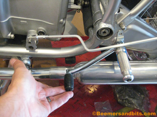
Time to cut (again).
And after some more threading, I am all set! I left some extra length on the rod just ‘in case’. Once i ride the bike and get a feel for the shifting and foot movements, i can adjust the lever as necessary. If there is too much rod, i can always shave some down. But for now, it is ready to go!


Let the wiring begin
I can’t be happier to have the bodywork back (and my garage back too!). I can finally start putting some overdue time in on the bike. The zen of wiring begins. A part of the build i actually enjoy problem solving.
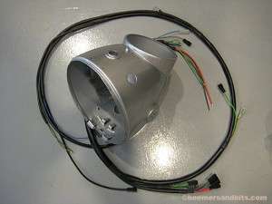
Instead of the old, original key switch, we are upgrading to a Rocky Point key ignition. The first step is installing the ‘doughnut’ retainer. You use the same bend-tabs for the ignition board but you bend the tabs on the giant washer instead. This is much easier to install when the headlight is off the bike.

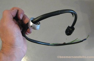
I then installed the chrome key housing cover. Installing the small spring on the black sliding cover was a bit tricky. That black slider needs to weave into the chrome cover and then you have to wrap the spring around the round tab that sticks out of the center of the headlight bucket. Again, another item easier to install when the headlight is off the bike.
Bending the tabs for the chrome cover is really tricky. An assortment of needle-nose pliers helps.

The speedometer is simple to install. Don’t forget the rubber gasket that goes between the headlight and the speedometer.
The orange turn signal indicator is simple to install as well.
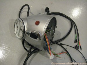
Don’t forget to thread the wires through the handlebar switch support piece before you install it into the headlight bucket.
And so it begins….

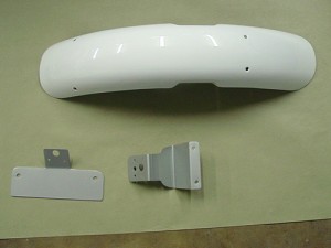
Paint work is done!
It is in route to me as I type this. I can wait to see it. I can finally fully assemble (and align) the forks and start wiring the headlight. I think it is spectacular… but then again, i’m biased!
Enjoy.


Back to bike building!!
The garage is done! Photos of the new bike-build-work-space to come ( i still need to tidy it up).
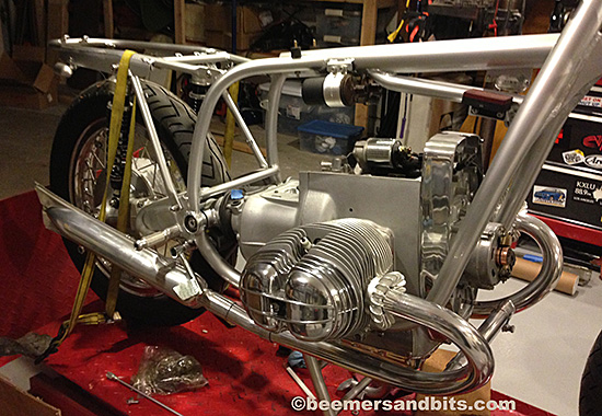
I started tinkering with the bike again. I have been DYING to mount the exhaust. Here is a small sneak peek of what it will look like. Some more tech tips and build updates coming soon!
Transmission Install
A Transmission install is actually not difficult.
Step #1 is making sure the swingarm is unmounted from the frame. It can remain connected to the shocks.
I then took caution to protect the frame:
![]()
Protection. Notice the rags too:
![]()
Time to prep the transmission. It helps if the shifter and the clutch arm are removed. In my case, i removed the shifter but left the clutch arm mounted:
![]()
Time to lube the splines. Make sure the splines are clean of dirt and grime. I use a BMW moly grease. It is sticky stuff. :![]()
Keeping the swingarm and rear wheel pulled back, gently lift the transmission into place. It may take a small wiggle here and there to get the splines to mate with the engine.
![]()
Make sure the top right bolt of the engine housing aligns properly with the transmission housing as you mate the splines into the clutch: ![]()
Time to tighten everything down.
You need a M8 nut and washer for the top right engine stud bolt.
a M8 x 40mm bolt and washer for the top left mount. (Note, i am not installing the BMW airbox. If i was, there is a retaining clip that mounts to the top left bolt along with a washer intended for the airbox).
a M8 X 85mm bolt, washer and nut for the bottom right mount
and a M8 x 40mm bolt and washer for the bottom left mount.
A 6mm hex socket and wrench does the trick along with a 13mm wrench/socket.
![]()
Lastly before you mount the swingarm, Make sure you attach the driveshaft boot. Notice the different ends of the boot. The round end is for the transmission, the oval/rectangular end is for the drive shaft![]() .
.
Next step… aligning and mounting the swing-arm… stay tuned!
Starter upgrade
A while back we ordered a new starter from Euro Moto Electrics.
It weighs half as much as the original BOSCH starter. About 6lbs lighter to be exact.

As a result, it doesn’t require the rear mounting bracket the heavy Bosch starters need (#2 in Photo).
The starter itself has threads where it connects near the flywheel so no need for the original nuts. You simply install the bolts from the flywheel side, and tighten the starter to the engine housing.
I plan on keeping the extra plastic cover and wire ring that holds it in place (#10 and #11). It will help keep some of the clutch dust contained.
