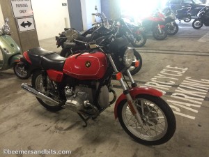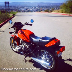
1980 Red R65 BMW
Although the directions are fairly clear, I went looking online for some installation help while installing a Boyer Brandsen electronic ignition on a R65 BMW that I am fixing up for a friend.
So… here is my install procedure. I am open to suggestions or tips but this is how my install went.
The carbs were tuned nicely before doing this install. The idle never seemed to get low enough which might indicate ignition problems, or tight valves but the valves were adjusted to spec.
I might suggest you get a spare bean can to perform this on. You end up modifying the original can somewhat and it may be difficult if you ever want to go back to stock.
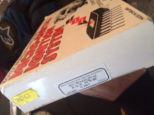
Boyer Brandsen Micro Digital ignition system.
I purchased this from Moto Bins in the UK and it arrived within a week.
Of course, you want to disconnect your negative cable from your battery before starting the procedure.
Gastank Removal is necessary for the wiring.
And remove the front engine timing cover.
I took the bean can cover off and front bearing before I started shooting photos. I was too eager to peek inside the bean can and see what is in there (It is my first time with a points in a can bike).
 I then removed the bean can from the bike.
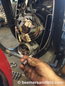
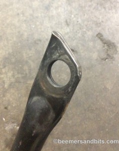
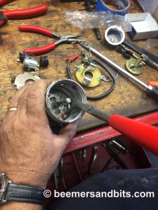
R65 Timing cover removal and removal of the ignition can.
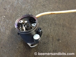
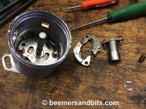
Removed points in can 1979 – 80 BMW ignition system
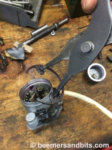
The large circlip needs to come out to disassemble the internals of the can.

The points come out easily and then you need to remove the points base plate.
Notice the ‘e’ circlip on the center shaft. Put a rag over the can when you remove that clip just in case it tries to go flying across the garage. The rag might catch it.

Points base plate removed.

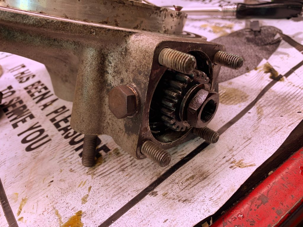
Circlip removed from the center shaft. The cam has to come off the shaft and you then need to remove the springs to slide off the contact breaker unit.
After you get the center cam removed, be careful with the very small circlips that hold the bob weights. Those need to come off to get the bob weights off.
Bob weights and center cam removed.
Now it is time for assembly of the electronic ignition!
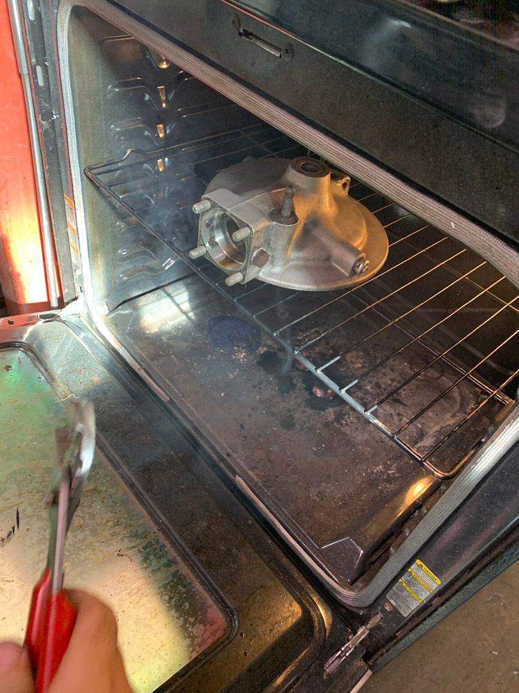
This was the first hiccup. The magnetic rotor does not fit into the housing properly without bending the spring mounting tabs. They are not easy to bend so it took some work.
Prepping for magnetic rotor install
Note the next photo. The tabs have to align with the notches where the tiny circlips were. The new rotor should sit flat, spin freely and the large clip should secure it to the center shaft.

Magnetic rotor installed
Another small snag. When the stator plate was installed with the cord going out the square hole, and the mounting screws were tightened, the magnetic rotor would not spin freely. It was a head scratcher in which everything was taken apart, put together again a few times. Finally by rotating the stator plate 180 degrees and making sure everything spins freely before securing the mounting screws, it happily went together.

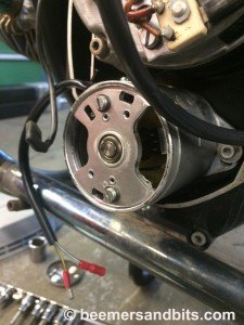
Install of the stator plate

Stator plate with cable going out rubber grommit hole vs square hole.
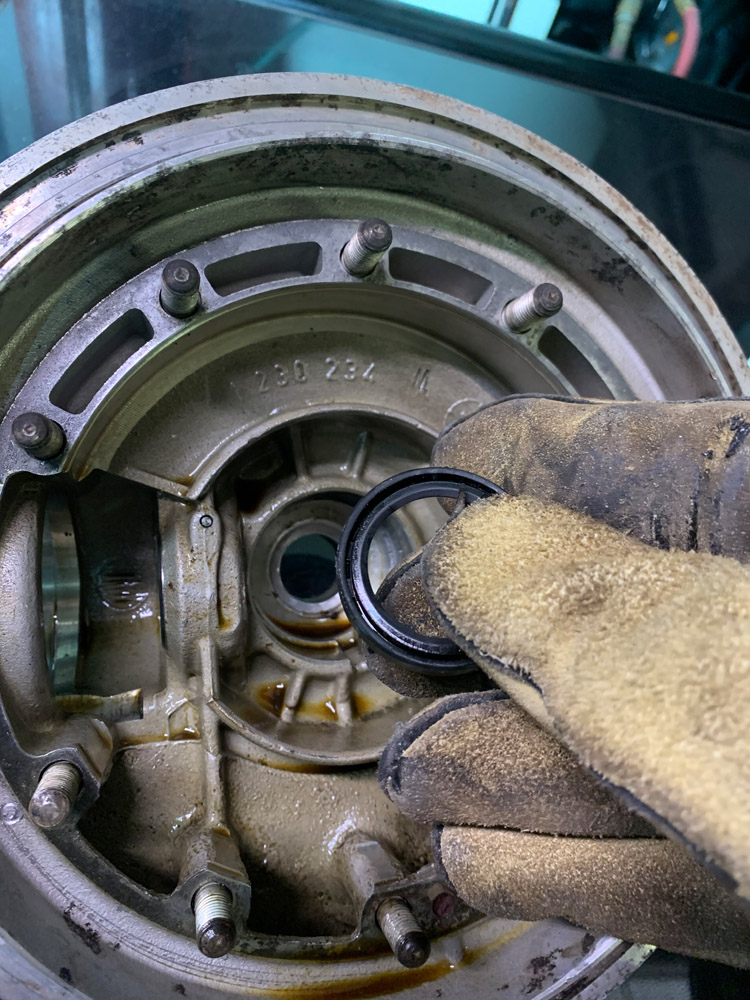
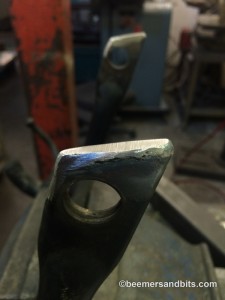
Now it is time to install the can back on the bike. 
The very large circlip went in and the center bearing plate installed.
I removed the diode board so I could route the wires behind it.

Removed Diode Board for wire routing
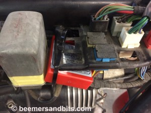
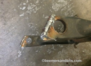
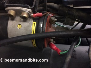
Control unit tucked and strapped to the frame components. It seemed like a tidy place to put it between the two coils.
The green wire connects with the existing green wire terminal on the rear ignition coil.
I also connected the ground wire to the coil mount bolt as well.
Not photographed but I made about a 12inch extension wire to connect the black wire from the ignition unit all the way to the other coil to replace the wire on the terminal that was connected to the old points condensor. For some reason, they put shrink tubing on the wiring as if they all connect in the same vicinity. It was either make an extension wire, or cut up the clean tubing so the black wire could reach over to the other coil.
It is all wired up and now time to set the timing.

I am not used to these flywheels so timing it took a bit of back and fourth. There is no ‘F’ mark on the flywheel. But there is the OT and a Z-dot.
Once I got it timed, and I fussed with the idle a bit, it ran great. Really smooth and more responsive then before.